| Lessons learned on the regular drill on 7/30/18. The “drill” was really an experiment on several evolutions that we had not conducted in the past.
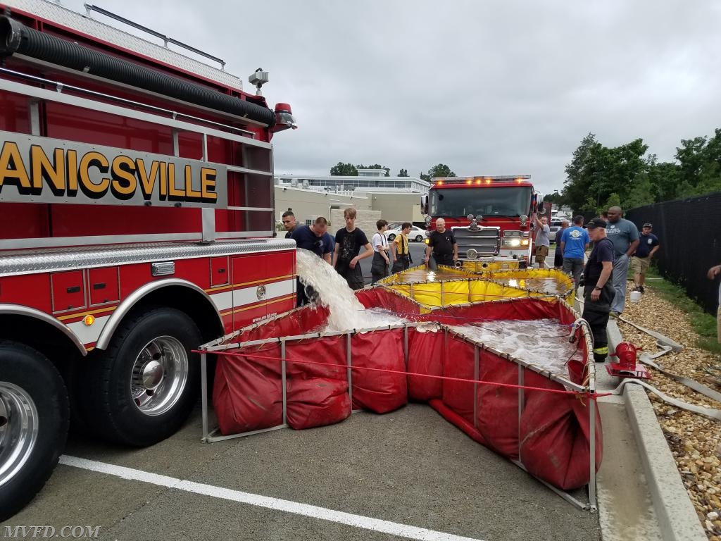
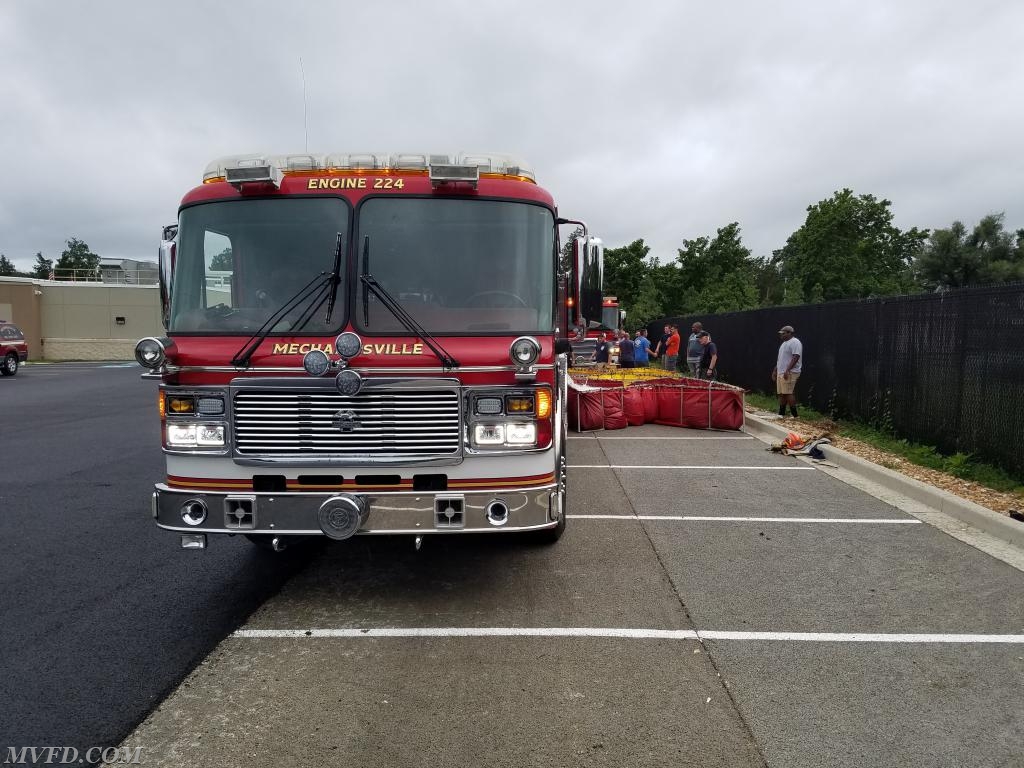
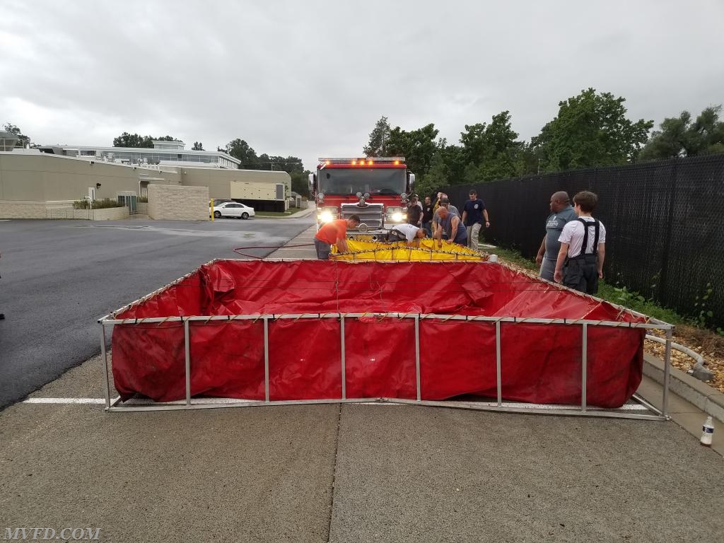
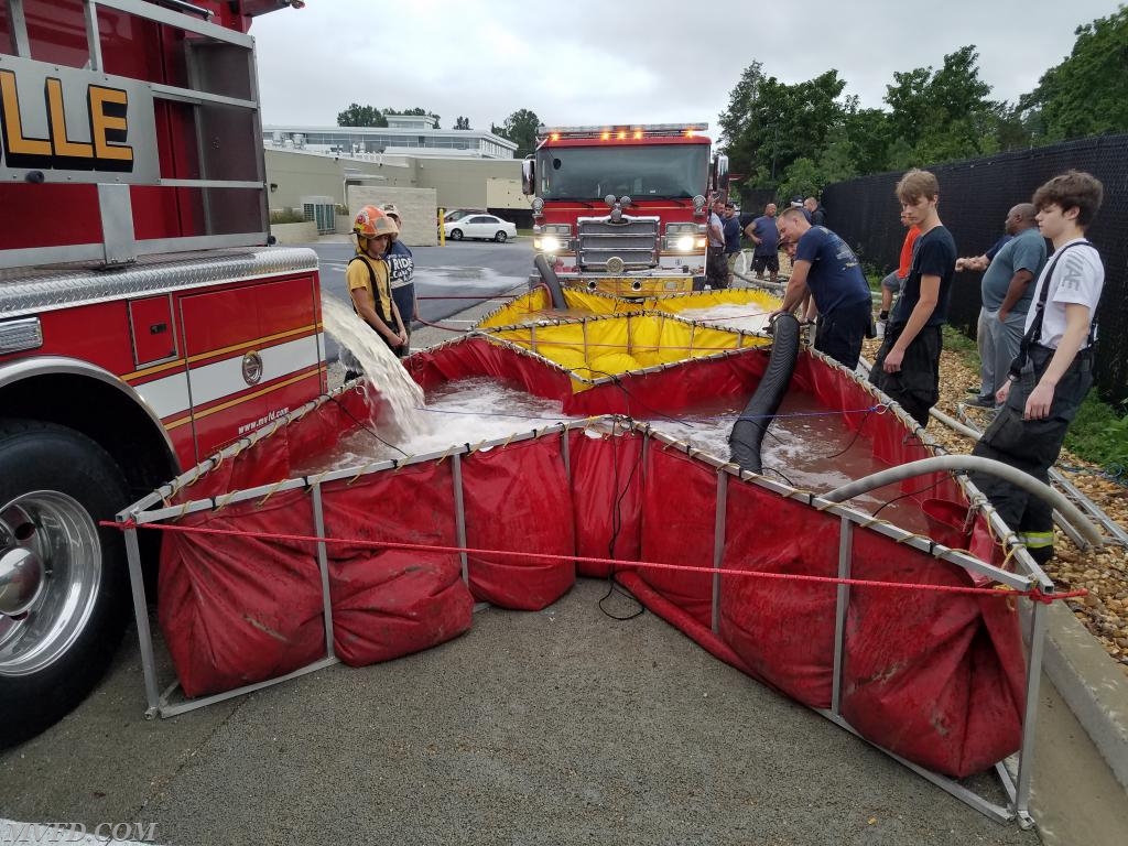
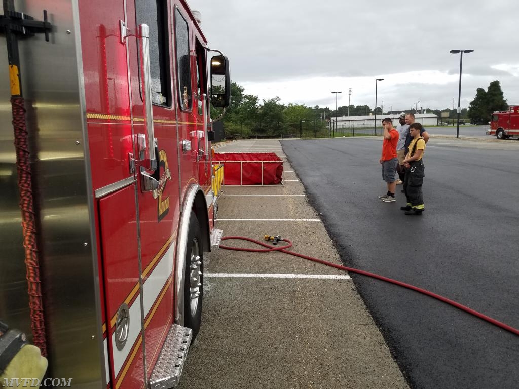
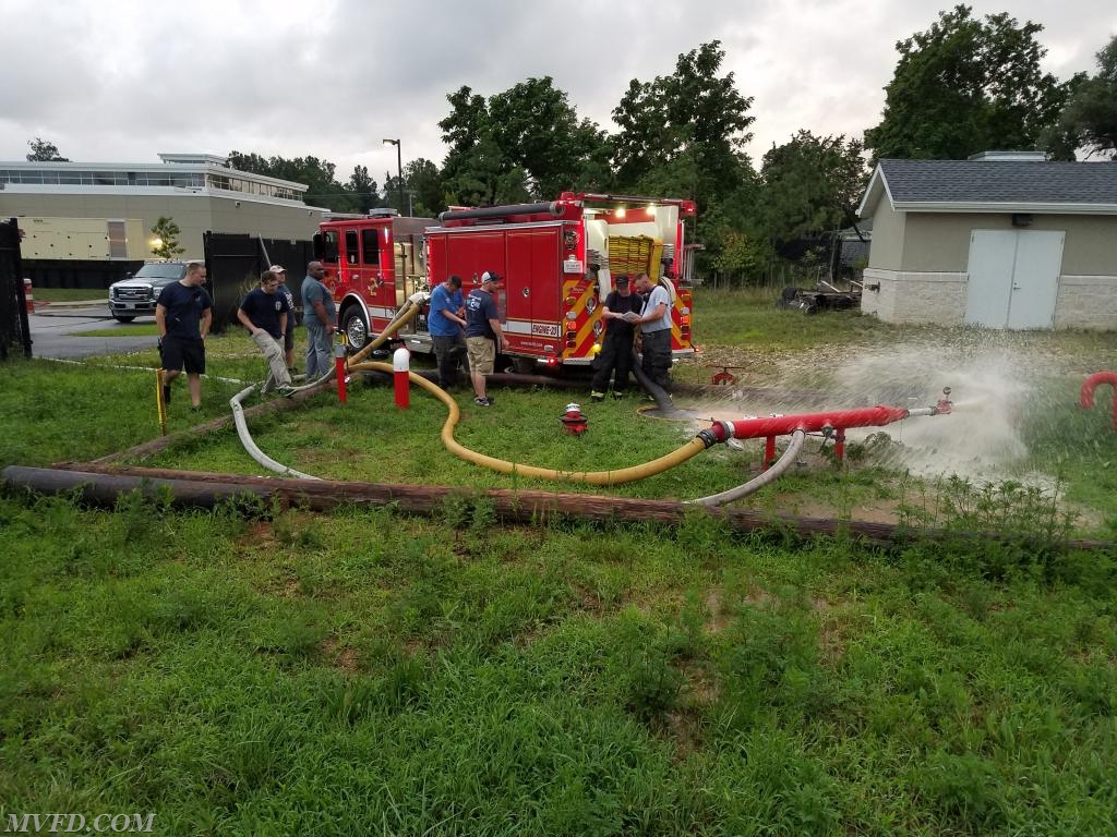
Evolution 1 – set up a single lane folding tank (SLT). In rare instances where a working fire incident is located on a roadway too narrow for shuttle apparatus to pass by the deployed folding tank, it may be necessary to restrict the opening of the tank to allow shuttle apparatus pull up beside the tank to side dump or pass by the tank to turn around beyond the tank. In that case the tank is positioned in front of the supply pumper and restricted to an open width of 8 feet (the width of the supply pumper). Tie offs are utilized to restricting the folding tank from opening to its full width. The photo shows the setup.
LESSONS LEARNED:
1. The capacity of the folding is reduced by approximately 50%. Our 3500 gal folding tank was filled by dumping about half a load of our 3000 gal tanker.
2. Ratchet straps are the best means to tie off of the tank as adjustments may be required as the folding tank fills.
3. Tie offs should be located at the top ends and middle of the tank. No tie offs are required at ground level.
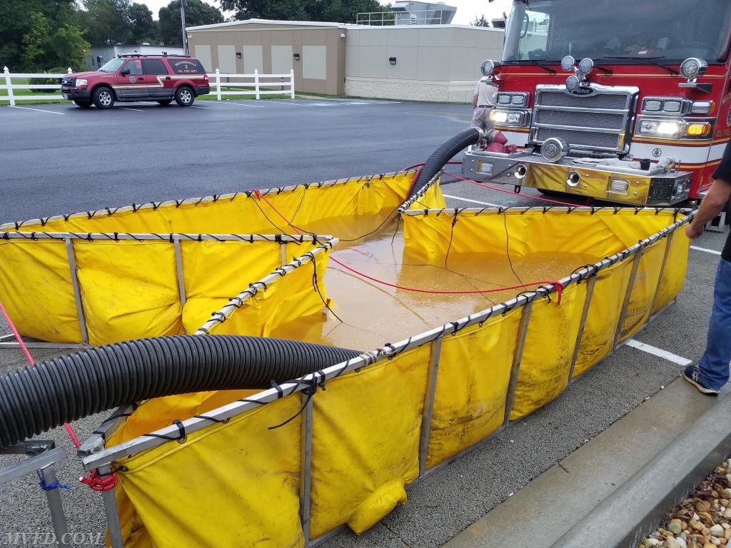
Evolution 2 – set up a second SLT to compensate for the reduced capacity of the first SLT. This evolution also required setting up a transfer siphon to transfer water to the folding tank with the supply pumper draft set up.
LESSONS LEARNED:
1. A low level strainer with a built in transfer siphon hookup is superior to the simple screw in transfer jet in transferring the water when the water depth reaches about 8 inches. Once the water level reached the top of the suction hose with the jet siphon, transfer ceased and the only water discharging from the transfer hose was the water being supplied by the supply pumper.
2. The higher the pressure on the transfer appliance, the faster the transfer rate. A pressure of 100 to 150 PSI works best.
3. The transfer siphon setup may require two sections of hard suction hose. One 10 foot and one 5 foot section were used in the drill.
4. The jet siphon has male threads and the low level strainer has female threads. The transfer suction hose must be positioned accordingly depending on the transfer appliance used.
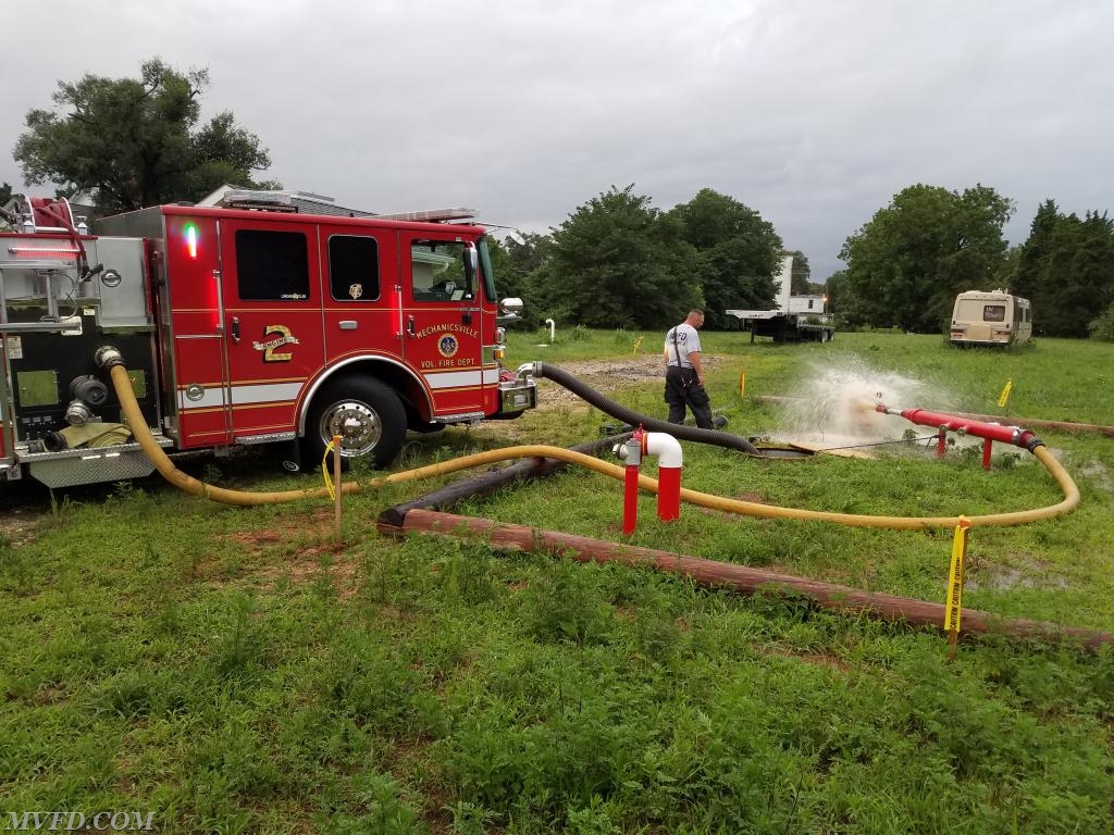
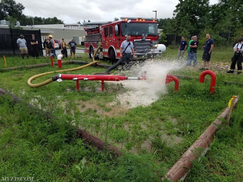
Evolution 3 – A drafting operation using the front intake on E-23. The pumper test site was utilized with 20 feet of hard suction and an approximately 10 foot lift. This is the standard NFPA setup for testing fire pumps. A 4 inch supply line was used to supply the test jig equipped with a stream shaper, an Akron pitot gage and a 2” tip. The tip pressure at pump cavitation was 55 PSI indicating an 881 GPM flow.
Evolution 4 – A drafting operation using the rear intake with 20 feet of hard suction and an approximately 10 foot lift. One 4 inch supply line and one 3” supply line was used to supply the test jig equipped with a stream shaper, an Akron pitot gage and a 2” tip. The tip pressure at pump cavitation was 80 PSI indicating a 1063 GPM flow.
LESSONS LEARNED
1. The rear intake has four 45° elbows while the front suction has four 45° elbows and two 90° elbows. This probably accounts for the different maximum flow results.
2. The time to first water with the air primer was approximately 30 to 45 seconds in either set up. Since the piping to the rear intake is longer, the prime time was slightly longer due to the additional air that had to be removed from the piping.
3. Note: The side suction tubes and the Q Max pump have a far superior drafting flow capability, easily 1500 to 1750 GPM, with the NFPA standard set up. The water flow path is direct into the impeller suction eye with no elbows.
Many thanks to all of the members who helped to set the multiple evolutions in the allotted 2 hour session. A job well done. |