The Mechanicsville VFD has made the use of the Humat valve a standard operating procedure on all rural water supply operations. In this evolution, the Humat acts as a high volume clapper valve siamese. The use of a siamese on the first in attack engine's supply line allows the use of multiple tankers or pumpers to supply the attack engine without interruption as the supply line is switched from one tanker to the other. This seamless switch from the first in tanker to the second in (and added alarm tankers) can continue until the supply pumper is set up with the folding tanks filled, the pump primed and the dischrge line ready to be hooked into the Humat. It avoids the commitment of a tanker as a nurse tanker and allows it to be used for water shuttle. An added advantage of having the first in tankers or the supply pumper lay an additional line to supply the Humat is the ability to stage them 50 to 100 feet back from the access driveway to the incident. Access to the incident is less likely to be blocked by pumpers or tankers allowing special service apparatus a clear entrance to the scene. It also allows a more optimum placement of the supply pumper and the folding tank(s) to minimize traffic congestion. Pumpers assigned to supply the Humat should stage 50 to 100 feet from the incident scene driveway and lay one section of hose to supply the Humat.
The goal is an uninterrupted water supply to the attack engine. A continuous water supply is critical if an interior attack is underway. Interior firefighters are at great risk if their water supply fails while they are conducting an aggressive attack on a large body of fire.
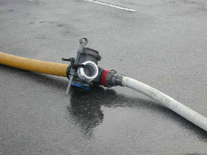
The photos show the sequential build up of the water supply to the attack engine starting with the layout of an uncharged supply line and ending with dual lines supplying the attack pumper.
|
|
|
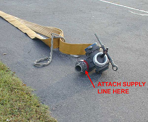 1. LAYOUT 1. LAYOUT
This photo shows the layout supply line as it looks when dropped at the hard surface entrance to the fire incident. If assigned to pick up the attack engine's supply line, DO NOT REMOVE THE HUMAT VALVE. The proper evolution is to pump into the Humat using a piece of 4 inch LDH or a 2 ½ or 3 inch supply line. Note the Humat has a 2 ½ x 4 Stortz adapter already preconnected (painted red) to allow the use of either 2 ½ inch or 4 inch hose. If using 4 inch hose, simply remove the adapter. If using 2 ½ or 3 inch hose, connect directly to the 2 ½ inch female swivel. No other action is required before charging the attack pumper's supply line. The Humat?s butterfly valve will already be closed so the water will flow to the attack pumper. A small amount of bypass leakage can be expected. A sharp wrap on the valve handle with the hand or foot will usually seat the valve and stop the leakage.
|
|
|
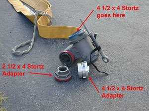
2. ADAPTERS DETACHED
This photo shows the two adapters carried on the Humat valve detached. The 2 ½ x 4 Stortz is shown detached from the Humat to allow connection of a 4 inch line. The 4 ½ x 4 Stortz is for use when a second line is used to supply the attack pumper through the Humat. It is normally attached to the Humat by a Velcro strap and is threaded into the 4 ½ inch female swivel (blue) on the Humat when needed. |
|
|
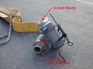
3. ADAPTERS ATTACHED
This photo shows the two adapters in their correct position. Note that the Humat can accept a 2 ½ inch or a 4 inch into the first intake (red) and a 4 inch into the second (blue) intake. |
|
|
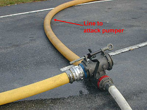
4. FIRST LINE 4 INCH
This photo shows the use of a 4 inch line as the first line from the supply pumper or tanker. Note that the 4 ½ x 4 Stortz adapter has been threaded into the intake to allow the Humat to accept a second 4 inch line. The 2 ½ x 4 Stortz adapter is available if the second line has a 2 ½ inch coupling. |
|
|
5. FIRST LINE 2 ½ INCH
This photo shows the use of a 2 ½ inch (or 3 inch) as the first line from the supply pumper or tanker. At this point the 4 ½ x 4 Stotz adapter would be threaded into the 4 ½ inch female swivel (blue) on the Humat. In this case the second line to the Humat has to be a 4 inch unless an additional 2 ½ x 4 Stortz adapter is available. |
|
|
6. TWO SIZES OF SUPPLY LINES
This photo shows the use of dual supply lines of two different sizes, one a 2 ½ (or 3 inch) and a 4 inch. The Humat clapper valve will switch to the line with the highest pressure regardless of the size of the line. For fully involved structures, the use of a 2 ½ inch supply line should be avoided. A section of 3 inch supply line will provide adequate water in this situation. |
|
|
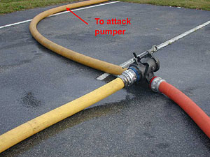
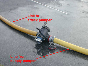
7. DUAL SUPPLY LINES
This photo shows the final set up position. Dual lines are in place using the Humat valve to siamese these lines together. The clapper valve built into the Humat is the key to this operation. The clapper valve automatically switches position to allow the tanker or pumper supplying the highest pressure to become the supply source. The second in tanker or pumper remains at idle with the pump in gear, line connected to the Humat and the discharge open (producing 25 to 50 psi). Pump RPM is raised (to produce 100 to 150 psi) just as the first in tanker runs out of water. It allows the lines to be unhooked from the supply tankers (when they are empty) without interruption of the supply from a second tanker or pumper hooked into the Humat. This feature is critical during the initial attack as the second in tanker can be hooked up and ready to take over supplying water as soon as the first in tanker is empty.In addition, the supply pumper at the folding tank can be set up and hooked in without interrupting the tanker operation.
|
|
|
Back to Water Supply
|
| |